CAD Help Center

CAD Problems? Search here.........

Wednesday, September 8, 2010

Download and Tutorials of SOLIDCast, OPTICast, FLOWCast

Here are the links to download the Software and Tutorials of SOLIDCast, OPTICast, FLOWCast AND THE


SOLIDCAST IS THE WORLD’S MOST POPULAR PC-BASED SOLIDIFICATION MODELING SYSTEM.

No other casting modeling program offers POWER, EASE OF USE and ACCURACY like SOLIDCast®

SOLIDCast® lets you see how your casting will solidify before you make pattern equipment, dies and costly mistakes. Pour your test castings on the computer, not on the foundry floor! Design gates, risers and test them out before making your first casting. Solidification modeling helps you to shorten lead times, produce higher quality and improve yield. All of this means lower costs, higher profits and improved marketability for your foundry.

     Investment Cast Steel Valve Body

SOLIDCast® can be used to simulate castings poured in gray iron, ductile iron, steel, aluminum, copper-base, magnesium, nickel-based and almost any other alloy. A database of several hundred alloys, with their properties, is included.

With SOLIDCast® you can simulate processes such as green sand, chemically-bonded sand, investment and permanent mold. You can use sleeves (insulating or exothermic), chills, hot topping, cooling channels, heating elements and just about anything else that is used in the metal casting process.

SOLIDCast® now contains the new Riser Design Wizard and Gating Design Wizard. These tools allow you rig new castings in just a few minutes from a 3D CAD model, using actual process data, not guesses based on simple geometry. Since casting alloy, mold material and actual process conditions are taken into account, there is no more accurate way to calculate gating and riser designs for castings.
With SOLIDCast® you can import 3D models from CAD, or build your own models without CAD.

     Ductile Iron Steering Knuckle

Graphics are the most sophisticated available, with fully movable 3D models, X-ray images, high-resolution color images and AVI video files. You can send movies to anyone with a Windows PC!

     Under-Riser Shrink in Gray Iron Casting

Source:

Download and learn Professional Version of BELTSTAT 7.0

Some of the friends are searching and asking for the free or demo versions of the BELTSTAT software from a long ago. So today here is the link for the Professional Version of BELTSTAT 7.0 as well as manual for BELTSTAT. here is the link to download the software.


Features available in the Professional Version of BELTSTAT:

Project Files
Project files are perhaps one of the most powerful features of BELTSTAT. This option automatically generates the following set of files, which represent the worst-case design conditions.
  • Fully Loaded - High Friction
  • Fully Loaded - Low Friction
  • Fully Loaded - Normal Friction
  • Empty - Normal Friction
  • Inclines Loaded - High Friction
  • Declines Loaded - Low Friction
The above files were created from a standard, but customizable, input window. Temperatures, belt weights, idler seal drags, and motor efficiency are just a few of the possible input variables. Each file represents a specific design condition such as: Maximum power requirement, regeneration conditions, maximum belt tension, and various others.
For example in the "Inclines Loaded - High Friction" case, the designer is trying to determine the absolute maximum power requirement that may be required. In this particular case the belt weight and idler seal drag are increased, while the ambient temperature and motor efficiency is slightly decreased. Additionally only the inclined (power consuming) sections of the belt are loaded with material.
A complete 3-page summary is then generated containing all relevant information from each of the six design cases.
Concave Curve Calculations
The vertical curve analysis routines have been completely redone in version 7.0. Detailed information on belt edge stresses, belt liftoff, and the belt center stresses is calculated. Minimum radii are shown for each condition (maximum center stress, minimum edge stress, belt liftoff, etc.). The recommended radii are given for each loading condition and the conveyor profile can instantly be updated at the click of a button (You can even round the radii up to the nearest 50 meters or whatever you want!). Problem areas are highlighted in RED.
Convex Curve Calculations
The convex curve analysis is similar to the concave routines except that idler loading is also considered. The current idler load rating is shown as well as the optimal idler spacing. Both the concave radii and the idler installation tolerances are included in the calculations.
Idler Life Calculations
This is another MAJOR new addition to version 7.0. Two calculation methods had been implemented. The first, is the standard CEMA methodology. Idler loading, and life calculations are given for each flight as well as an "average idler life" for the entire conveyor. This is a very powerful number since it gives the designer a feel for the total life of the conveyor system.
The second idler calculation method is based off the presimeca calculations. This method calculated the actual bearing load on each bearing (wing and center rolls) and then computes the idler life for each flight. The complete SKF bearing tables have also been included (6200, 6300, and 6400 series bearings).
Belt Flap
The belt flap feature is simply a quick check to determine if belt flap may be an issue on the return side of the belt. Based on the belt tensions, belt weight, and idler spacing, the plot shows the ratio between the idlers rotating frequency and the natural vibrating frequency of the belt (as calculated by string theory). An integer frequency ratio represent a undesirable, possible resonance condition.
Belt Roll Calculations - Load On/Off
Belt roll calculations give the required number of belt rolls, roll weight, and roll dimensions for a single, cassette, or racetrack roll configuration. The load on/off feature shows the conveyor's power consumption and belt tensions as the conveyor is loaded and unloaded.
Material Loading
Another simple, but useful little tool for graphically viewing the material load for almost any idler configuration is the material loading tool. You can even input a horizontal banking angle and watch the material "shift" to one side or the other. Both the actual edge distance, as well as the CEMA percent loading are given.
Microsoft Word Reports
Everyone's going to like this one! Now BELTSTAT can directly export the BSO output file to a formatted Microsoft Word document. You can then E-mail it to who ever you wish. Furthermore, you will have the option of printing out pulley, idler, motor and other summary pages, which you can directly fax to equipment suppliers for quotations. This is another must have feature.
AutoCAD / Excel Importing and Exporting Profiles
Excel CSV files and AutoCAD DFX files can be imported directly into BELTSTAT. Likewise, BELTSTAT conveyor profiles can be exported as DFX or CSV files, which can be opened in AutoCAD or Excel.
Belt Feeder Design
The belt feeder design is a powerful new tool in version 7.0. Built off currently accepted design theory and equations, the power consumption, feeder loads, rathole sizing, and other design information can be determined. Both the initial startup, and the steady state flow conditions are determined. Required hopper half angles are computed for both conical and slotted feeder geometry's to ensure a steady mass flow design.
Pulley Calculations
BELTSTAT contains full and DETAILED pulley and shaft design information. The standard CEMA B105 pulley specification is included as well as detailed engineering calculations for the shaft that include:
  1. X-Y Bearing Reactions
  2. Kb & Kt stress concentration factors at turndowns
  3. Maximum Shear and Von Misses Stresses
  4. Static and Dynamic Safety Factors
  5. SFK 22500-23100 Series pillow block data
Belt Turnover Stresses
Calculate transition distances, edge stresses, and safety factors with this powerful design feature. BELTSTAT even includes stresses from bending moments in the turnover, in addition to the normal twist stresses.
Belt Splice Design
This feature may go beyond the scope of work for most engineers, but we find it very useful. All one, two, three, and four step splice designs are included. In fact, BELTSTAT will automatically optimize your splice design and provide the most common and useful splice information such as:
  • Belt pitch
  • Cable diameters and breaking strengths
  • G/D ratios
  • Belt weights
  • Overall splice dimensions
Over 20 new design features and improvements have been added in version 7.0. These features help you save time, and make the BELTSTAT software easier than ever to use.
Word and Excel are registered trademarks of Microsoft Corporation. AutoCAD is a registered trademark of Autodesk, Inc. All other brand names, product names, or trademarks belong to their respective holders.

Source:

Sunday, August 29, 2010

Installation and configuration of Solidworks 2007 or Solidworks 2008 on Windows 7 x64 bit

Dear CAD HELP CENTER readers welcome back after a long time with a new solution.
Today I will describe How to install and configure the Solidworks 2007 on Windows 7 x64 bit.

Earlier I have got some queried regarding the support of Solidworks 2007 in Windows 7. A lot of my friends are in confusion weather Solidworks 2007 will work or not in Windows 7 if they will upgrade their operating system. Officially only Solidworks 2009, Solidworks 2010 and Solidworks 2011 are support Windows 7 (32 & 64 bit). Solidworks 2007 and Solidworks 2008 are not supports Windows 7 officially.

But we need not to worry about the supports because there are a lot of ways to do this job.

Officially Solidworks 2007 & 2008 is not supported but we can install and use both versions in Windows 7 (32 & 64 bit).

Here we will see that how can we install & configure Solidworks 2007 in Windows 7 x64 bit.

First of all install Solidworks 2007 or 2008 like same as in Windows XP. (Remember that Solidworks 2007 or 2008 (32 bit) can be installed in both Windows 7 (32 & 64 bit). Solidworks 2007 or 2008 (64 bit) can be installed in only Windows 7 64 bit.
After installation you will find the Solidworks icon on the Desktop screen. Do not run the program just after installation because it will show the compatibility error and will not run.

Right Click on the Solidworks icon and select Properties as shown in below picture.


1. Click on Compatibility Tab.
2. Check mark Run this program in compatibility mode.
3. Select the Windows type you want for Compatibility Mode. Select Windows XP (Service Pack 2)
4. Then if you want this setting for all users then Click on the option Change Setting for all users.
5. Thereafter Click on Apply to apply this setting.
6. Then Click OK button.


After that run the Solidworks by double clicking on the Solidworks icon or right and select Open. This will run the program make Solidworks to run in compatible mode. In between the process the compatibility wizard can ask you to do this or not in that case select the next button. Compatibility wizard will show you the below screen after completion.


Now you can create or Open any Part or Assembly file. Click on New.

Select Part and then Click on OK button.


Now Solidworks 2007 or Solidworks 2008 is ready for use. Make whatever you want.


So if anyone using Windows XP or Windows Vista and want to upgrade their operating system to Windows 7 then you can upgrade. This will improve your working speed and performance.
If anyone has any issue or any other help then leave your comments.


CAD HELP CENTER value your feedback's.
Cheers.

Wednesday, May 19, 2010

Solidworks 2010 HotKeys for Windows 7

Hi CAD HELP CENTER readers there are some of the hotkeys of Solidworks 2010 for Windows 7 to improve your working speed.


Hotkeys
•WIN + Up Arrow or WIN + Down Arrow = toggle between window states, Maximized,
Restore and Minimized
•WIN + Shift + Left or Right Arrow = move window to another monitor
•WIN + 1, 2, 3, 4 or 5 = Launch the corresponding application on the Task Bar
•WIN + P = Projector and video output settings
•WIN + X = Mobility Center – Several convenient controls such as projector, WiFi, etc.
•WIN + T = Task Bar navigation via arrow keys
•WIN + D = Show Desktop
•WIN + E = Windows Explorer
•WIN + L = Lock Windows
•WIN + “+” = Magnifying Glass
•Win + Tab = cycle through the open application using Aero Flip
•Alt + Tab = cycle through the open applications
•Ctrl + Tab = cycle through the open documents within an application
•Ctrl + Application Icon = cycle through the open documents within the application
•Ctrl + Shift + Application Icon = Run application as Administrator
•Shift + Application Icon = Run a new instance of an application
•Alt + F4 = Terminate the active application
•Ctrl + Shift + Escape = Windows Task Manager
•Ctrl + C = copy
•Ctrl + X = cut
•Ctrl + V = paste
•Ctrl + Drag = copy
•Shift + Drag = move

Performance Settings
•Windows 7 has been designed for 64bit. Running the operating system as a 64bit OS
will give you performance gains as well as access to unlimited memory.
For applications not supported on 64bit, try Windows XP mode.
•You can monitor RAM, Processor and Video performance via the Resource and
Performance Monitor. To access type “resource” or “performance” in the Windows
Search bar.
•Turn off “Eye Candy” if performance is suffering. Right click on the Desktop and
choose Personalize. Under Themes, choose Windows Classic or Windows Basic.
•Tune the Power Settings to suite your working environment. Set your screen saver and
sleep settings to longer durations so you do not have to constantly wake the machine.
•For faster shutdowns, you can change what the power icon does. Right click the Sleep,
Shutdown, Hibernate button and choose properties. There is a drop down menu where
you can change its default functionality.
•Completely disable Hibernate. Access the Command Prompt and type
powercfg /hibernate off.
•With SATA drives you can turn on write caching to gain a performance increase.
However, make sure that you are running either a laptop batter or UPS to avoid
data loss.

Saturday, May 1, 2010

Step by Step Installation Process of UG NX 7.0 x64 bit on Windows XP x64 bit.

Dear CAD HELP CENTER readers as we all know that last year in September 2009 Siemens PLM Software is proudly introduced NX 7 in market. From the same day everyone is in search to get this latest NX 7 with HD3D tools & Synchronous Technology and now I have got this and hope so you also have got it.
The new version of UG NX 7.0 is available for both Windows x32 bit and x64 bit platforms.
The full package is a combined bundle of multi modules includes Solid Modeling, Sheet metal Designing, Surface Designing, Digital Mock-Up (DMU), Kinematics, Finite Element Analysis, Machining, Circuit Designing and many more.....

You are at right place if you are searching to get help regarding installation of Unigraphics NX 7 or can say UG NX 7. This guide will help you to install and configure license file for UG NX 7 on Windows XP x64 bit.
So get ready to know how to install or configure UG NX 7 in Windows XP x64 bit.

Here in this post I am describing my experience of installation of UG NX 7.0 x64 bit on my desktop computer in Windows XP Professional x64 Edition Service Pack 2. First of all I want to share with you that whatever media I have got is saying that Files on this media are intended for use on the Windows XP 64 Bit platform only. So I am not conformed till now whether this will work on Windows Vista X64 bit or Windows 7 x64 bit. I will check this in near future and if you need this then you can just check at your end or you can leave your comments.
After complete installation of UG NX 7 x64 bit on my computer I realize that the overall process of installation is very easy.

So First of all mount the DVD in the drive and run the Launch.exe. This will Show you the NX 7.0 Software Installation menu. From here you can View Documentation, Install License Server, Install NX or can get Composite Host ID.


Now click on Install NX. This will start the installation of unigraphics NX 7 on your Computer or Laptop or Machine.Now you have to Choose Setup Language. The default language is English but you can select your choice.(Currently UG NX 7 is supporting Chinese Simplified & Traditional, English, French, German, Italian, Japanese, Korean, Russian and Spanish) This is only Setup Language.


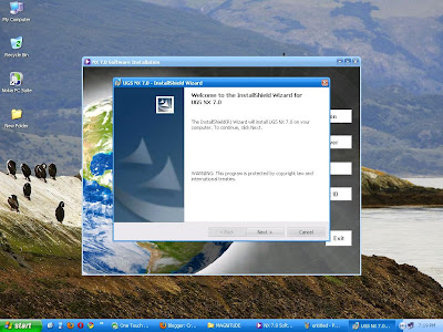
Now you will see the  Welcome to InstallShield Wizard for UGS NX 7.0.


Now Click on Next Button. This will Show you Setup Type Menu.


Select Typical and Click on Next button. and you will see the Destination Folder Menu.


Keep the Destination Folder as it is and Click on Next button. This will show you Licensing Menu and ask you to Enter Server Name or a License File.


This will be like 28000@complete_name for my Computer or 28000@Your Host Name for your computer. You can check your computer name Here. This will show you NX 7.0 Language Selection menu.


Select the Language in which you want to install the UG NX 7. This is the Language in which program will run after installation. English is Default one, you just select yours and then Click on Next Button.


After that the setup will ask you to review or change the Installation Setting. If the setting is OK then click on Install Button or if anything wrong then click back and repeat the above process to reset all. 
After Clicking on Install Button the Setup will start Installing UGS NX 7.0.


After installing the Setup will show you the InstallShield Wizard Completed. Now Click on Finish.


Now you have to Configure your License File to run the UG NX 7.0, so for this Copy your License File in the UGS installation Directory. This will be C:\Program Files\UGS\NX 7.0\UGFLEXLM


Now you have to run the lmtools.exe (You can do this by following methods)
  1. Start->All Programs->UGS NX 7.0->NX Licensing Tools->lmtools
  2. Start->Run->C:\Program Files\UGS\NX 7.0\UGFLEXLM\lmtools.exe
  3. Go to the above shown file location and double click on lmtools.exe
Now follow the below precess to configure license services:
  1. Go to Config Service Tab.
  2. Enter Service Name (Like: UG NX 7.0)
  3. Click on Browse Button and select the lmgrd.exe file. ( The path should be like : C:\Program Files\UGS\NX 7.0\UGFLEXLM\lmgrd.exe)
  4. Click on Browse Button and select the License File. ( The path should be like : C:\Program Files\UGS\NX 7.0\UGFLEXLM\nx7.lic)
  5. Click on Browse Button and select the Debug Log File. ( The path should be like : C:\Program Files\UGS\NX 7.0\UGFLEXLM\log.txt) (If the file is not in directory then you can make a new text file with log.txt name.
  6. Check the Use Services.
  7. Check the Start Server at Power Up.
  8. Now Save the Services by pressing the Save Service Button.
  9. Now go to Start/Stop/Reread Tab.
  10. Check the license services installed on this computer. This should show you UG NX 7.0.
  11. Now click on Start Server Button and exit the lmtools.exe by clicking on the cross mark on upper right hand corner.


Now your program is ready to launch. just go to: 

Start->All Programs->UGS NX 7.0->NX 7.0


Hope that this will help you to install and configure the new version of Unigraphics (UG NX 7.0)
If any query or feedback or suggestion, then let me know via comments.

CAD Help Center Updates

Thursday, April 15, 2010

Step by Step Installation Process of Catia V6R2009 x64 bit on Windows XP x64 bit.

Dear CAD HELP CENTER readers as we all know that Dassault Systemes already released the new CAD platform named Catia V6R2009 and Catia V6R2010 (both in x32 bit and x64 bit) which is a combined bundle of multi modules includes Solid Modeling, Sheet metal Designing, Surface Designing, Digital Mock-Up (DMU), Kinematics, Finite Element Analysis, Machining, Equipment & Systems, Logic Designing and many more.....

The most advantages and must needed feature of Catia V6 is inbuilt PLM version 2. Yes this one have inbuilt PLM so that you will not bother anymore for any file management issues or linking problems.

So here in this post I am describing my experience of installation of Catia V6R2009 x64 bit on my desktop computer in Windows XP Professional x64 Edition Service Pack 2.
The same can be checked in the below picture.


As mentioned above this is a x64 bit version of Catia V6R2009 and it can be only installed on x64 bit operating systems means Windows XP x64, Windows Vista x64 and Windows 7 x64.

Here I have installed in only Windows XP professional x64 bit and hope that it will also work in other x64 bit Windows.

After complete installation of Catia V6R2009 x64 bit on my computer I realize that the overall process of installation is easy but some of the third party applications required before starting installation. These third party software's are needed to be preinstalled on your machine or computer. Here are a list of supporting software's required before installing:

  1. Microsoft Core XML Services version 6 component (MSXML6) : you can download this from http://www.microsoft.com/downloads
  2. The second one is Java version 5 or Higher : http://java.com or Download Java Runtime Environment 64-bit here 
  3. Microsoft .NET Framework 3.0 (or higher).or Download Microsoft .NET Framework 3.0 (or higher) 
After installation of these above applications you can start installation of Catia V6R2009 x64 bit.
First of all mount the DVD in the drive and run the setup.exe.


Here if you have not installed the MSXML6 on your machine or computer, setup will show you the error screen like below:


After installation of MSXML6 setup will show you the welcome screen of Catia V6 Installation.On welcome screen click next button.


On next screen setup will ask you for a nodelock license key. If you have then press import certificate and complete the process. Then click next button.


Choose destination folder for installation. The default one will be like C:\Program Files\Dassault Systemes\B205 or you can choose your own location.Then click next button.


As there is not any directory like mentioned above so you have to create a directory as shown below. Click on YES and then click next button.


Then define or choose Environment Location. The default one will be like C:\Documents and Settings\All Users\Application Data\DassaultSystemes\CATEnv


Keep it as it is and click next button. This will ask you to create Environment Directory, click on Yes button and then click next button.


 In setup type select Complete and click next button.


During Video MJPEG Codec check mark the button to install the codec and click next button.


Keep the Communication Port same as recommended and click next button.


Then it will ask you to define JAVA directory, then give the java home path like C:\Program Files\Java\jre6 


where you have installed the JAVA 6 and click next button.


Select the shortcuts you want and click next button.


Then Setup will show you the files to be copied. if you want to modify anything then you can click on back button and make the modifications. If you want to continue then click on Install button.


Then you will see a summery of all the information you provided during installation. Click on Install button.


Now Setup will start the installation. 


Just wait for completion and click on Finish button (Uncheck the launch Catia V6R2009 now)


Copy JS0GROUP.dll (From Crack/JS0GROUP.dll) and overwrite the original one in the following folder: C:\Program Files\Dassault Systemes\B205\win_b64\code\bin

Now Run the Catia V6R2009. This will show you an error of license manager as shown below.

Now select at least one configuration or product from the available list and restart the session to take settings into account.


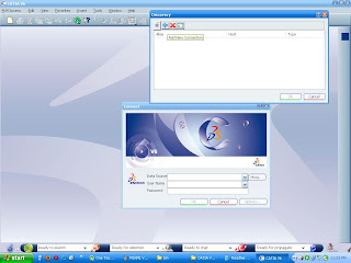
To run CATIA V6R2009 you have to point so called Provider Data Source. It may be 3D XML, Enovia or Smart Team databases.

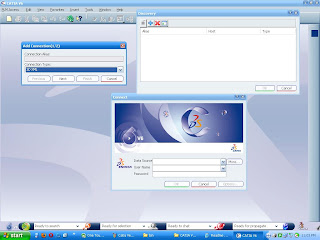
For example (choosing 3D XML) press More->Add New Connection.


During add connection choose Connection Type as the '3DXML' and click on next button.

 
and for 3D XML path choose this path and click finish button:
C:\Program Files\Dassault Systemes\B205\win_b64\resources\3DXMLModels\Sample.3dxml


Now click on the OK button on data source dialog box.Now you will see connect screen.
Please check the data source path (This will be) as below:
C:\Program Files\Dassault Systemes\B205\win_b64\resources\3DXMLModels\Sample.3dxml (3DXML) 

and then click on OK button:    


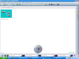
After this you will see the Root of Sample.3DXML screen, here you can browse the existing Enovia3DLive_Quad product.


or you can create your own new product by clicking on new button or via PLM Access menu.Select the product type you want to make (like Mechanical Product) and click on Next button.


In Mechanical Product Tab Select Product or 3D Shape. Here Product Means new assembly or product and 3D shape means Part if we compare it with earlier versions of Catia till V5R20. Then give a part number and description and click on Finish Button.


Now you are ready to make any new product which can be a single representation or have multiple representations. You can go in Feature or sketcher mode via double clicking on representation or part body.
If you want to change the module then click on the 3DS Icon or button on lower left corner in light green color. you can swap visible space by clicking on the fold icon on right hand lower corner beside 3DS Catia logo.


One noticeable thing in Catia V6 is the there are no more parts. There are only representations and products.

Hope that this will help you to install and understand the new version of CATIA V5R2009 with PLM Version 2.0

If any query or feedback or suggestion, then let me know via comments.

CAD Help Center Updates